![]()
![]()
![]()
![]()
![]()
![]()
![]()
![]()
![]()
![]()
![]()
![]()
![]()
![]()
![]()
![]()
Boat: Rhumb Do
Date: October 2016
PROBLEM: Fridge partially defrosting, leaving pool of water in bottom.
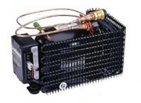
My small top loading fridge is situated under one of the saloon seats, with the Danfoss BD35F compressor, 101NO210 electronic control box and condenser in an adjacent under seat locker, along with a Waeco Mobitronic EPS 100B rectifier.
The compressor is dual voltage, taking as it's supply, either 12 or 24 volts DC.
At sea, the fridge uses the 12 volt supply direct from the house bank batteries via a switch and fuse. When on 240 volt AC shore supply, the rectifier supplies 24 volts DC to the electronic control box, which switches off the 12 volt supply and runs on the now 24 volts. It does this automatically with no manual intervention.
It's a long drawn out story which I have sort of described in the log this month, but what I now know is the Danfoss compressor is fitted with a little known, and very useful self diagnostics chip, the description of which I will paste below.
Danfoss BD35F Compressor.
The Danfoss BD35 and BD50 compressors have their own fault diagnostic allowing easy fault finding. The fault code will only be shown when the compressor fails to start or stops.
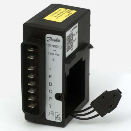
Find the electronic control box pictured on the left - it will be fitted to the side of the compressor
Start by Linking out the Thermostat
To ensure the thermostat is not causing problems put a link out between C and T terminals this will force the compressor to run continually during testing.
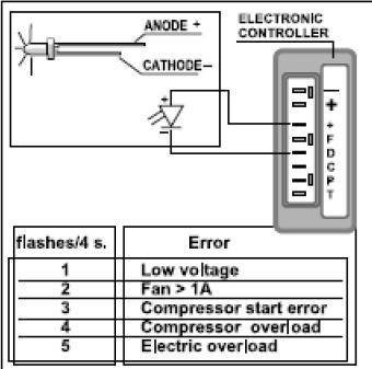
Connect the LED fault diagnosis circuit
If an LED light is connected between the small positive (+) and D terminal on the control box, as shown in the diagram , it will flash an error code if the compressor refuses to start.
Interpreting the results
1 Flash = Low Voltage
Indicates low voltage. Voltage at the incoming power terminals on the Danfoss controller has dropped to less than 10.4v (22.8v). Voltage must rise above the cut‐in voltage of 11.7v (24.2v) before the compressor will attempt a re‐start. NOTE: If the initial power applied at start‐up is less than 11.8v (24.3v), there will be no fault code flashing on the diagnostic LED, but the compressor will not attempt to start until the voltage has risen above 11.7v (24.3v).
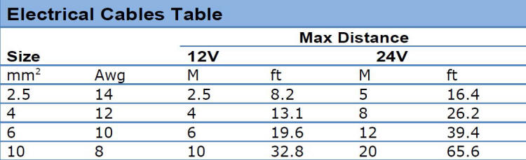
a) Confirm the wire dimension is correct
If this is a new installation check the wire sizing:
b) Test the Power supply
To properly test the power supply to a Danfoss powered 12v or 24v system, the following testing procedure must be carried out. This will establish whether the power supply feeding the system is free of bad, loose and/or high-resistance connections.
Reading the voltage on the panel or at the batteries is meaningless, as is the fact of a new installation or new batteries.
Size and the capacity of the battery bank is irrelevant.
1. Turn off the breaker (or remove the fuse) supplying DC power to the system.
2. Unplug one of the thermostat leads at the controller.
3. Using a multi-meter, read the DC voltage at the battery terminal(s).
4. Connect the multi-meter reading DC voltage to the power terminals (+ and -) on the controller so that it can be left connected and monitored.
5. Turn on the breaker (or install the fuse) to the system.
6. Check that the voltage is the same as the voltage seen at the battery terminals.
7. Whilst watching the multi-meter, reconnect the thermostat lead and monitor the voltage continuously before, during, and after the compressor starts or attempts to start.
Interpreting power supply results
If the power supply is free of loose, bad, and/or high resistance connections, the voltage reading at 5 above will stay very stable and only drop slightly when the compressor starts. As a general rule, on a 12v system the reading should not drop below 12v.
If, when the compressor attempts to start, the voltage reading drops significantly, a bad electrical connection should be suspected. If the voltage drop is sufficient to fall below the 10.5v (23v) cut-off built in to the controller, the compressor will stop. (At this point the voltage may return to it s original reading.) The fan or pump will continue to run for approx. 45 seconds and then the compressor will attempt a re-start. If the voltage is then above 11.5v (23.5v) the compressor will start or attempt to re-start again.
NOTE:
If the multi-meter being used is a digital model that is slow to react, the voltage may drop below 10.5v (23v) and then recover too quickly to register on the meter. This can lead to the situation where the compressor starts then stops from low voltage, the voltage returns to its original value, and there being no significant drop on the meter.If the compressor starts and runs OK but stops after a short while, the voltage may be gradually dropping towards and below the 10.5v (23v) cut-off point.
This should be easily identified on the meter.
If the nature of the fault is such that the voltage reading at 5 above drops below 10.5v (23v) even before the compressor attempts to start, a very bad electrical connection must be suspected. This is because even the small load of the fan or pump relay, both less than 0.5 amp (0.25 amp), is seemingly sufficient to reduce the voltage considerably.
What to look for
A loose and/or high-resistance connection can be anywhere in the supply between the batteries and the controller. i.e. a bad breaker or fuse, a loose or corroded screw connection, a poorly made or corroded crimp connection, a damaged section of wire, etc. A good place to look first is the negative (ground) connection, especially on a European-built boat. These tend to be multiple, common connections that are added to over time.
2 Flashes = Fan draws more than 1 amp
a. Air cooled systems
The fan is faulty and drawing more than 1 amp.
Unplug the fan or water pump and restart the compressor.
You will need to replace the fan.
b. Water cooled systems
Unplug the water pump and restart the compressor to confirm the compressor will now run.
If the system now runs it means the pump is drawing more than 1 Amp. The system should be set up with the pump connected via a relay or pump interface to prevent this happening.
If it is not, add a relay to the system.
If there is a relay/pump interface already fitted it may have developed a fault and should be replaced.
3 Flashes = Compressor Start Error
This could still be a voltage error, due to a power surge or similar, or (more usually) a faulty compressor controller.
First turn off the power to the unit for 1 minute to let the system reset. Turn the power back on and see if the fridge runs.
If the system still fails to start, replace electronic controller or send it to a reputable dealer for testing.
4 Flashes = Compressor Overload
Indicates that the compressor cannot reach minimum speed of 1,850 RPM.
System has a blockage, possibly moisture that has entered the refrigeration system or the compressor has seized (unlikely).
Send the controller to a reputable dealer for testing.
5 Flashes = Electric Overload
Indicates that the electronics heat sink has exceeded 212 deg F (100 deg C). This can be due to an overcharge of refrigerant, water in the system, or excessive ambient temperatures combined with a compressor operating under extreme load. A re‐start will be attempted when heat sink has cooled to 170 deg F (80 deg C).
A guru of small BD compressors says:
Troubleshooting one of these units is simple once it is understood that it is very unlikely that this type compressor will ever fail. BD compressors have almost an unlimited life because their control module protects it from failures common in other hermetic electric compressors. The number one cause for a Danfoss BD compressor module to terminate a compressor start up is a low voltage spike. Voltage spikes at module are not always visible with a meter and can be present on any [boat/motorhome]. Unstable voltage is why the module must receive power direct from battery buss using correct size wiring, fuses, circuit breaker and switches that allow no voltage drop. When the compressor is correctly wired to the battery buss it will absorb voltage surges like a very large electrical capacitor reducing module electronics false starts and module failures.
In my case, the low-voltage code was flashed on the LED, despite connecting 4 different power supplies which by-passed the boats power supply cables. After some days, it dawned on me that the only common factor present during all tests and trial runs was a 12" long manufacturers cable to the control box and to the thermostat. When I replaced those, the 'fridge started to work again. So, it is imperative that ALL the wiring between batteries and control box are checked.